« Takaisin
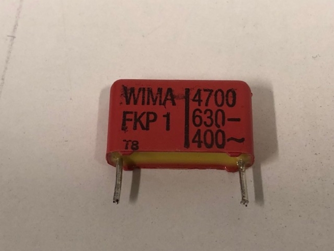


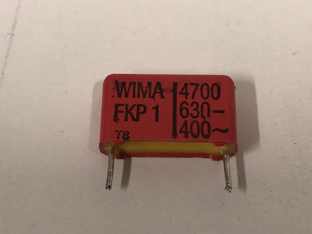
Kondensaattori WIMA FKP1 / kpl
Hinta:1.00 €

WIMA FKP 1 Polypropylene (PP) Capacitors for Very High Pulse Applications with Metal Foil Electrodes and Metallized Internal Series Connection in PCM 15 mm to 52.5 mm. Capacitances from 100 pF to 4.7 mF. Rated Voltages from 400 VDC to 6000 VDC. Special Features Electrical Data ˜ Extremely high pulse duty ˜ Self-healing ˜ Internal series connection ˜ Very low dissipation factor ˜ Negative capacitance change versus temperature ˜ AEC-Q200 qualified for PCM 37.5 mm (for larger box sizes on request) ˜ According to RoHS 2011/65/EU Typical Applications For high pulse and high frequency applications e.g. ˜ Switch mode power supplies ˜ Converters in drives and power electronics ˜ Deflection systems in monitors and TV-sets ˜ Electronic ballasts Construction Dielectric: Polypropylene (PP) film Capacitor electrodes: Aluminium foil and double-sided metallized plastic film Internal construction: Plastic film Metal foil electrode Metal contact layer (schoopage) Terminating wire Electrode carrier plastic film metallized on both sides Encapsulation: Solvent-resistant, flame-retardant plastic case with epoxy resin seal, UL 94 V-0 Terminations: Tinned wire. Marking: Colour: Red. Marking: Black. Dielectric absorption: 0.05 % Insulation resistance at +20+ C: C T 0.1 mF: 1 x 10⁵ M¸ C 0.1 mF: 30 000 sec (M¸ x mF) Measuring voltage: 100 V/1 min. Voltage derating: A voltage derating factor of 1.35 % per K must be applied from +85+ C for DC voltages and from +75+ C for AC voltages Reliability: Operational life 300 000 hours Failure rate 1 fit (0.5 x Ur and 40+ C) Capacitance range: 100 pF to 4.7 mF (E12-values on request) Rated voltages: 400 VDC, 630 VDC, 1000 VDC, 1250 VDC, 1600 VDC, 2000 VDC, 4000 VDC, 6000 VDC Capacitance tolerances: ±20%, ±10%, ±5% (other tolerances are available subject to special enquiry) Operating temperature range: –55+ C to +105+ C Climatic test category: 55/100/56 in accordance with IEC Test voltage: 2 sec PCM 4000 VDC 4000 VDC 6000 VDC 37.5 37.5 2 Ur 2 Ur 2 Ur 1.6 Ur 1.6 Ur 1.2 Ur Dissipation factors at +20+ C: tan d at f C 0.1 mF 0.1 mF P C 1.0 mF C 1.0 mF 1 kHz 5 x10⁻⁴ 5 x 10⁻⁴ 5 x 10⁻⁴ 10 kHz 6 x10⁻⁴ 6 x 10⁻⁴ – 100 kHz 10 x 10-4 – – Maximum pulse rise time: Capacitance max. pulse rise time V/msec at TA < 40) C pF/mF 400 VDC 630 VDC 1000 VDC 1250 VDC 1600 VDC 2000 VDC 4000 VDC 6000 VDC 100 ... 220 – – – – 56000 56000 – – 330 ... 680 – – – – 51000 56000 56000 56000 1000 ... 2200 29000 29000 29000 29000 46000 51000 51000 51000 3300 ... 6800 9000 14000 27000 29000 29000 29000 29000 29000 0.01 ... 0.022 9000 11000 11000 11000 11000 13000 13000 13000 0.033 ... 0.068 9000 11000 11000 11000 11000 11000 13000 13000 0.1 ... 0.22 7000 11000 11000 11000 11000 11000 13000 13000 0.33 ... 0.68 6000 10000 11000 11000 11000 11000 – – 1.0 ... 2.2 5000 6600 8300 9500 11000 – – – 3.3 ... 4.7 2500 – – – – – – – Mechanical Tests Pull test on pins: d T 0.8 l: 10 N in direction of pins d > 0.8 l: 20 N in direction of pins according to IEC 60068-2-21 Vibration: 6 hours at 10 ... 2000 Hz and 0.75 mm displacement amplitude or 10 g in accordance with IEC 60068-2-6 Low air density: 1kPa = 10 mbar in accordance with IEC 60068-2-13 Bump test: 4000 bumps at 390 m/sec2 in accordance with IEC 60068-2-29 Packing Available taped and reeled up to and including case size 15 x 26 x 31.5 / PCM 27.5 mm. Detailed taping information and graphs at the end of the catalogue. For further details and graphs please refer to Technical Information. 80 06.21 Continuation General Data D Capacitance 400 VDC/250 VAC* 630 VDC/400 VAC* W H L PCM** Part number W H L PCM** Part number 1000 pF 5 11 18 15 FKP1G011004B_ _ _ _ _ _ 5 11 18 15 FKP1J011004B_ _ _ _ _ _ 1500 „ 5 11 18 15 FKP1G011504B_ _ _ _ _ _ 5 11 18 15 FKP1J011504B_ _ _ _ _ _ 2200 „ 5 11 18 15 FKP1G012204B_ _ _ _ _ _ 5 11 18 15 FKP1J012204B_ _ _ _ _ _ 3300 „ 5 11 18 15 FKP1G013304B_ _ _ _ _ _ 5 11 18 15 FKP1J013304B_ _ _ _ _ _ 4700 „ 5 11 18 15 FKP1G014704B_ _ _ _ _ _ 5 11 18 15 FKP1J014704B_ _ _ _ _ _ 6800 „ 5 11 18 15 FKP1G016804B_ _ _ _ _ _ 6 12.5 18 15 FKP1J016804C_ _ _ _ _ _ 0.01 mF 5 11 18 15 FKP1G021004B_ _ _ _ _ _ 7 14 18 15 FKP1J021004D_ _ _ _ _ _ 5 14 26.5 22.5 FKP1J021005A_ _ _ _ _ _ 0.015 „ 6 12.5 18 15 FKP1G021504C_ _ _ _ _ _ 8 15 18 15 FKP1J021504F_ _ _ _ _ _ 6 15 26.5 22.5 FKP1J021505B_ _ _ _ _ _ 0.022 „ 7 14 18 15 FKP1G022204D_ _ _ _ _ _ 7 16.5 26.5 22.5 FKP1J022205D_ _ _ _ _ _ 5 14 26.5 22.5 FKP1G022205A_ _ _ _ _ _ 0.033 „ 8 15 18 15 FKP1G023304F_ _ _ _ _ _ 8.5 18.5 26.5 22.5 FKP1J023305F_ _ _ _ _ _ 6 15 26.5 22.5 FKP1G023305B_ _ _ _ _ _ 0.047 „ 7 16.5 26.5 22.5 FKP1G024705D_ _ _ _ _ _ 10.5 20.5 26.5 22.5 FKP1J024705H_ _ _ _ _ _ 9 19 31.5 27.5 FKP1J024706A_ _ _ _ _ _ 0.068 „ 8.5 18.5 26.5 22.5 FKP1G026805F_ _ _ _ _ _ 11 21 31.5 27.5 FKP1J026806B_ _ _ _ _ _ 9 19 41.5 37.5 FKP1J026807A_ _ _ _ _ _ 0.1 mF 10.5 20.5 26.5 22.5 FKP1G031005H_ _ _ _ _ _ 13 24 31.5 27.5 FKP1J031006D_ _ _ _ _ _ 9 19 31.5 27.5 FKP1G031006A_ _ _ _ _ _ 11 22 41.5 37.5 FKP1J031007B_ _ _ _ _ _ 0.15 „ 11 21 31.5 27.5 FKP1G031506B_ _ _ _ _ _ 13 24 41.5 37.5 FKP1J031507C_ _ _ _ _ _ 0.22 „ 13 24 31.5 27.5 FKP1G032206D_ _ _ _ _ _ 15 26 41.5 37.5 FKP1J032207D_ _ _ _ _ _ 11 22 41.5 37.5 FKP1G032207B_ _ _ _ _ _ 0.33 „ 13 24 41.5 37.5 FKP1G033307C_ _ _ _ _ _ 19 32 41.5 37.5 FKP1J033307F_ _ _ _ _ _ 0.47 „ 17 29 41.5 37.5 FKP1G034707E_ _ _ _ _ _ 20 39.5 41.5 37.5 FKP1J034707G_ _ _ _ _ _ 0.68 „ 19 32 41.5 37.5 FKP1G036807F_ _ _ _ _ _ 24 45.5 41.5 37.5 FKP1J036807H_ _ _ _ _ _ 1.0 mF 20 39.5 41.5 37.5 FKP1G041007G_ _ _ _ _ _ 35 50 41.5 37.5 FKP1J041007J_ _ _ _ _ _ 1.5 „ 31 46 41.5 37.5 FKP1G041507I_ _ _ _ _ _ 40 55 41.5 37.5 FKP1J041507K_ _ _ _ _ _ 35 50 57 52.5 FKP1J041509F_ _ _ _ _ _ 2.2 „ 35 50 41.5 37.5 FKP1G042207J_ _ _ _ _ _ 45 55 57 52.5 FKP1J042209H_ _ _ _ _ _ 3.3 „ 35 50 57 52.5 FKP1G043309F_ _ _ _ _ _ 4.7 „ 45 65 57 52.5 FKP1G044709J_ _ _ _ _ _ * AC voltages: f T 1000 Hz; 1.4 x Urms + UDC T Ur ** PCM = Printed circuit module = pin spacing Dims. in mm. Ionisation inception level in isolated cases may be lower than admissible rated AC voltage. Rights reserved to amend design data without prior notification. WIMA FKP 1 Continuation page 81 Part number completeion: Version code: 2-pin = 00 4-pin = D4 Tolerance: 20 % = M 10 % = K 5 % = J Packing: bulk = S Pin length: 6-2 = SD Taped version see page 161. 81 06.21 Continuation General Data D Capacitance 1000 VDC/600 VAC* W H L PCM** Part number 1000 pF 5 11 18 15 FKP1O111004B_ _ _ _ _ _ 1500 „ 5 11 18 15 FKP1O111504B_ _ _ _ _ _ 2200 „ 5 11 18 15 FKP1O112204B_ _ _ _ _ _ 3300 „ 5 11 18 15 FKP1O113304B_ _ _ _ _ _ 4700 „ 6 12.5 18 15 FKP1O114704C_ _ _ _ _ _ 6800 „ 7 14 18 15 FKP1O116804D_ _ _ _ _ _ 0.01 mF 8 15 18 15 FKP1O121004F_ _ _ _ _ _ 6 15 26.5 22.5 FKP1O121005B_ _ _ _ _ _ 0.015 „ 6 15 26.5 22.5 FKP1O121505B_ _ _ _ _ _ 0.022 „ 8.5 18.5 26.5 22.5 FKP1O122205F_ _ _ _ _ _ 0.033 „ 10.5 20.5 26.5 22.5 FKP1O123305H_ _ _ _ _ _ 9 19 31.5 27.5 FKP1O123306A_ _ _ _ _ _ 0.047 „ 11 21 31.5 27.5 FKP1O124706B_ _ _ _ _ _ 0.068 „ 13 24 31.5 27.5 FKP1O126806D_ _ _ _ _ _ 11 22 41.5 37.5 FKP1O126807B_ _ _ _ _ _ 0.1 mF 13 24 41.5 37.5 FKP1O131007C_ _ _ _ _ _ 0.15 „ 15 26 41.5 37.5 FKP1O131507D_ _ _ _ _ _ 0.22 „ 19 32 41.5 37.5 FKP1O132207F_ _ _ _ _ _ 0.33 „ 20 39.5 41.5 37.5 FKP1O133307G_ _ _ _ _ _ 0.47 „ 31 46 41.5 37.5 FKP1O134707I_ _ _ _ _ _ 0.68 „ 35 50 41.5 37.5 FKP1O136807J_ _ _ _ _ _ 1.0 mF 40 55 41.5 37.5 FKP1O141007K_ _ _ _ _ _ 35 50 57 52.5 FKP1O141009F_ _ _ _ _ _ 1.5 „ 45 55 57 52.5 FKP1O141509H_ _ _ _ _ _ 2.2 „ 45 65 57 52.5 FKP1O142209J_ _ _ _ _ _ * AC voltages: f T 1000 Hz; 1.4 x Urms + UDC T Ur ** PCM = Printed circuit module = pin spacing Dims. in mm. Ionisation inception level in isolated cases may be lower than admissible rated AC voltage. 2-pin version 4-pin version Rights reserved to amend design data without prior notification Continuation page 82 WIMA FKP 1 P d PCM 0.8 15 - 27.5 1.0 37.5 pin pin c c W PCM b P d c 17 37.5 10 1.0 0.4 19 37.5 10 1.0 0.4 20 37.5 12.5 1.0 0.4 24 37.5 12.5 1.0 0.4 31 37.5 20 1.0 0.4 35 37.5 20 1.0 0.4 40 37.5 20 1.0 0.4 35 52.5 20 1.2 0.8 45 52.5 20 1.2 0.8 Part number completion: Version code: 2-pin = 00 4-pin = D4 Tolerance: 20 % = M 10 % = K 5 % = J Packing: bulk = S Pin length: 6-2 = SD Taped version see page 161. pin 82 06.21 Continuation General Data D WIMA FKP 1 Capacitance 1250 VDC/600 VAC* 1600 VDC/650 VAC* W H L PCM** Part number W H L PCM** Part number 100 pF 5 11 18 15 FKP1T001004B_ _ _ _ _ _ 150 „ 5 11 18 15 FKP1T001504B_ _ _ _ _ _ 220 „ 5 11 18 15 FKP1T002204B_ _ _ _ _ _ 330 „ 5 11 18 15 FKP1T003304B_ _ _ _ _ _ 470 „ 5 11 18 15 FKP1T004704B_ _ _ _ _ _ 680 „ 5 11 18 15 FKP1T006804B_ _ _ _ _ _ 1000 pF 5 11 18 15 FKP1R011004B_ _ _ _ _ _ 6 12.5 18 15 FKP1T011004C_ _ _ _ _ _ 5 14 26.5 22.5 FKP1T011005A_ _ _ _ _ _ 1500 „ 5 11 18 15 FKP1R011504B_ _ _ _ _ _ 7 14 18 15 FKP1T011504D_ _ _ _ _ _ 5 14 26.5 22.5 FKP1T011505A_ _ _ _ _ _ 2200 „ 5 11 18 15 FKP1R012204B_ _ _ _ _ _ 8 15 18 15 FKP1T012204F_ _ _ _ _ _ 5 14 26.5 22.5 FKP1T012205A_ _ _ _ _ _ 3300 „ 6 12.5 18 15 FKP1R013304C_ _ _ _ _ _ 6 15 26.5 22.5 FKP1T013305B_ _ _ _ _ _ 4700 „ 7 14 18 15 FKP1R014704D_ _ _ _ _ _ 7 16.5 26.5 22.5 FKP1T014705D_ _ _ _ _ _ 6800 „ 8 15 18 15 FKP1R016804F_ _ _ _ _ _ 8.5 18.5 26.5 22.5 FKP1T016805F_ _ _ _ _ _ 5 14 26.5 22.5 FKP1R016805A_ _ _ _ _ _ 0.01 mF 7 16.5 26.5 22.5 FKP1R021005D_ _ _ _ _ _ 10.5 20.5 26.5 22.5 FKP1T021005H_ _ _ _ _ _ 0.015 „ 8.5 18.5 26.5 22.5 FKP1R021505F_ _ _ _ _ _ 11 21 31.5 27.5 FKP1T021506B_ _ _ _ _ _ 0.022 „ 10.5 20.5 26.5 22.5 FKP1R022205H_ _ _ _ _ _ 11 21 31.5 27.5 FKP1T022206B_ _ _ _ _ _ 0.033 „ 11 21 31.5 27.5 FKP1R023306B_ _ _ _ _ _ 13 24 31.5 27.5 FKP1T023306D_ _ _ _ _ _ 9 19 41.5 37.5 FKP1R023307A_ _ _ _ _ _ 13 24 41.5 37.5 FKP1T023307C_ _ _ _ _ _ 0.047 „ 13 24 31.5 27.5 FKP1R024706D_ _ _ _ _ _ 13 24 41.5 37.5 FKP1T024707C_ _ _ _ _ _ 11 22 41.5 37.5 FKP1R024707B_ _ _ _ _ _ 0.068 „ 11 22 41.5 37.5 FKP1R026807B_ _ _ _ _ _ 15 26 41.5 37.5 FKP1T026807D_ _ _ _ _ _ 0.1 mF 15 26 41.5 37.5 FKP1R031007D_ _ _ _ _ _ 17 29 41.5 37.5 FKP1T031007E_ _ _ _ _ _ 0.15 „ 17 29 41.5 37.5 FKP1R031507E_ _ _ _ _ _ 20 39.5 41.5 37.5 FKP1T031507G_ _ _ _ _ _ 0.22 „ 19 32 41.5 37.5 FKP1R032207F_ _ _ _ _ _ 24 45.5 41.5 37.5 FKP1T032207H_ _ _ _ _ _ 0.33 „ 24 45.5 41.5 37.5 FKP1R033307H_ _ _ _ _ _ 31 46 41.5 37.5 FKP1T033307I_ _ _ _ _ _ 0.47 „ 31 46 41.5 37.5 FKP1R034707I_ _ _ _ _ _ 40 55 41.5 37.5 FKP1T034707K_ _ _ _ _ _ 0.68 „ 40 55 41.5 37.5 FKP1R036807K_ _ _ _ _ _ 35 50 57 52.5 FKP1T036809F_ _ _ _ _ _ 1.0 mF 35 50 57 52.5 FKP1R041009F_ _ _ _ _ _ 45 55 57 52.5 FKP1T041009H_ _ _ _ _ _ 1.5 „ 45 65 57 52.5 FKP1R041509J_ _ _ _ _ _ * AC voltages: f T 1000 Hz; 1.4 x Urms + UDC T Ur ** PCM = Printed circuit module = pin spacing Dims. in mm. Ionisation inception level in isolated cases may be lower than admissible rated AC voltage. Rights reserved to amend design data without prior notification WIMA FKP 1 Part number completion: Version code: 2-pin = 00 4-pin = D4 Tolerance: 20 % = M 10 % = K 5 % = J Packing: bulk = S Pin length: 6-2 = SD Taped version see page 161. Continuation page 83 83 06.21 Continuation General Data D WIMA FKP 1 Capacitance 2000 VDC/700 VAC* 4000 VDC/700 VAC* W H L PCM** Part number W H L PCM** Part number 100 pF 5 11 18 15 FKP1U001004B_ _ _ _ _ _ 150 „ 5 11 18 15 FKP1U001504B_ _ _ _ _ _ 220 „ 5 11 18 15 FKP1U002204B_ _ _ _ _ _ 330 „ 6 12.5 18 15 FKP1U003304C_ _ _ _ _ _ 470 „ 6 12.5 18 15 FKP1U004704C_ _ _ _ _ _ 5 14 26.5 22.5 FKP1X004705A_ _ _ _ _ _ 680 „ 6 12.5 18 15 FKP1U006804C_ _ _ _ _ _ 5 14 26.5 22.5 FKP1X006805A_ _ _ _ _ _ 1000 pF 7 14 18 15 FKP1U011004D_ _ _ _ _ _ 5 14 26.5 22.5 FKP1X011005A_ _ _ _ _ _ 5 14 26.5 22.5 FKP1U011005A_ _ _ _ _ _ 1500 „ 6 15 26.5 22.5 FKP1U011505B_ _ _ _ _ _ 7 16.5 26.5 22.5 FKP1X011505D_ _ _ _ _ _ 2200 „ 7 16.5 26.5 22.5 FKP1U012205D_ _ _ _ _ _ 8.5 18.5 26.5 22.5 FKP1X012205F_ _ _ _ _ _ 3300 „ 7 16.5 26.5 22.5 FKP1U013305D_ _ _ _ _ _ 10.5 20.5 26.5 22.5 FKP1X013305H_ _ _ _ _ _ 4700 „ 8.5 18.5 26.5 22.5 FKP1U014705F_ _ _ _ _ _ 11 21 31.5 27.5 FKP1X014706B_ _ _ _ _ _ 6800 „ 10.5 20.5 26.5 22.5 FKP1U016805H_ _ _ _ _ _ 13 24 31.5 27.5 FKP1X016806D_ _ _ _ _ _ 0.01 mF 11 21 31.5 27.5 FKP1U021006B_ _ _ _ _ _ 15 26 31.5 27.5 FKP1X021006F_ _ _ _ _ _ 0.015 „ 13 24 31.5 27.5 FKP1U021506D_ _ _ _ _ _ 13 24 41.5 37.5 FKP1X021507C_ _ _ _ _ _ 0.022 „ 15 26 31.5 27.5 FKP1U022206F_ _ _ _ _ _ 17 29 41.5 37.5 FKP1X022207E_ _ _ _ _ _ 13 24 41.5 37.5 FKP1U022207C_ _ _ _ _ _ 0.033 „ 13 24 41.5 37.5 FKP1U023307C_ _ _ _ _ _ 20 39.5 41.5 37.5 FKP1X023307G_ _ _ _ _ _ 0.047 „ 17 29 41.5 37.5 FKP1U024707E_ _ _ _ _ _ 24 45.5 41.5 37.5 FKP1X024707H_ _ _ _ _ _ 0.068 „ 19 32 41.5 37.5 FKP1U026807F_ _ _ _ _ _ 31 46 41.5 37.5 FKP1X026807I_ _ _ _ _ _ 0.1 mF 20 39.5 41.5 37.5 FKP1U031007G_ _ _ _ _ _ 35 50 41.5 37.5 FKP1X031007J_ _ _ _ _ _ 0.15 „ 24 45.5 41.5 37.5 FKP1U031507H_ _ _ _ _ _ 40 55 41.5 37.5 FKP1X031507K_ _ _ _ _ _ 0.22 „ 35 50 41.5 37.5 FKP1U032207J_ _ _ _ _ _ 45 55 57 52.5 FKP1X032209H_ _ _ _ _ _ 0.33 „ 40 55 41.5 37.5 FKP1U033307K_ _ _ _ _ _ 0.47 „ 45 55 57 52.5 FKP1U034709H_ _ _ _ _ _ 0.68 „ 45 65 57 52.5 FKP1U036809J_ _ _ _ _ _ * AC voltages: f T 1000 Hz; 1.4 x Urms + UDC T Ur ** PCM = Printed circuit module = pin spacing Dims. in mm. Ionisation inception level in isolated cases may be lower than admissible rated AC voltage. 2-pin version 4-pin version Rights reserved to amend design data without prior notificationn. WIMA FKP 1 P d PCM 0.8 15 - 27.5 1.0 37.5 pin pin pin c c W PCM b P d c 17 37.5 10 1.0 0.4 19 37.5 10 1.0 0.4 20 37.5 12.5 1.0 0.4 24 37.5 12.5 1.0 0.4 31 37.5 20 1.0 0.4 35 37.5 20 1.0 0.4 40 37.5 20 1.0 0.4 35 52.5 20 1.2 0.8 45 52.5 20 1.2 0.8 Part number completion: Version code: 2-pin = 00 4-pin = D4 Tolerance: 20 % = M 10 % = K 5 % = J Packing: bulk = S Pin length: 6-2 = SD Taped version see page 161. Continuation page 84 84 06.21 Continuation General Data D Capacitance 6000 VDC/700 VAC* W H L PCM** Part number Dims. in mm. 470 pF 5 14 26.5 22.5 FKP1Y004705A_ _ _ _ _ _ Ionisation inception level in isolated cases may 680 „ 5 14 26.5 22.5 FKP1Y006805A_ _ _ _ _ _ be lower than admissible rated AC voltage. 1000 pF 5 14 26.5 22.5 FKP1Y011005A_ _ _ _ _ _ 1500 „ 7 16.5 26.5 22.5 FKP1Y011505D_ _ _ _ _ _ 2200 „ 10.5 20.5 26.5 22.5 FKP1Y012205H_ _ _ _ _ _ 3300 „ 10.5 20.5 26.5 22.5 FKP1Y013305H_ _ _ _ _ _ 4700 „ 11 21 31.5 27.5 FKP1Y014706B_ _ _ _ _ _ 6800 „ 13 24 31.5 27.5 FKP1Y016806D_ _ _ _ _ _ 0.01 mF 15 26 31.5 27.5 FKP1Y021006F_ _ _ _ _ _ 0.015 „ 13 24 41.5 37.5 FKP1Y021507C_ _ _ _ _ _ 0.022 „ 17 29 41.5 37.5 FKP1Y022207E_ _ _ _ _ _ 0.033 „ 20 39.5 41.5 37.5 FKP1Y023307G_ _ _ _ _ _ 0.047 „ 24 45.5 41.5 37.5 FKP1Y024707H_ _ _ _ _ _ 0.068 „ 31 46 41.5 37.5 FKP1Y026807I_ _ _ _ _ _ 0.1 mF 35 50 41.5 37.5 FKP1Y031007J_ _ _ _ _ _ 0.15 „ 40 55 41.5 37.5 FKP1Y031507K_ _ _ _ _ _ 0.22 „ 45 55 57 52.5 FKP1Y032209H_ _ _ _ _ _ * AC voltages: f T 1000 Hz; 1.4 x Urms + UDC T Ur ** PCM = Printed circuit module = pin spacing Rights reserved to amend design data without prior notificationn. WIMA FKP 1 Part number completion: Version code: 2-pin = 00 4-pin = D4 Tolerance: 20 % = M 10 % = K 5 % = J Packing: bulk = S Pin length: 6-2 = SD Taped version see page 161. Impedance change with frequency (general guide). 10 10 10 f/Hz 6 3 5 7 7 8 7 5 3 7 5 3 10 1 0.1 0.01 Z -- -- -- -- -- 470 pF 1500 pF 6800 pF 0.015 µF 0.033 µF 100 pF -- PCM 15 10 10 10 f/Hz 6 3 5 7 7 8 7 5 3 7 5 3 10 1 0.1 0.01 Z -- -- -- -- -- -- . -- 680 pF 1000 pF 2200 pF 4700 pF 0.01 0 µF 022 0.047 µF µF PCM 22.5 10 10 10 f/Hz 6 3 5 7 7 8 7 5 3 7 5 3 1 0.1 0.01 0.001 Z PCM 27.5 -- -- -- -- -- -- -- 4700 pF 0.01 0.022 µF µF 0.033 µF 0.047 µF 0.068 0.22 µF µF 10 10 10 f/Hz 6 3 5 7 7 8 7 5 3 7 5 3 1 0.1 0.01 0.001 Z -- -- -- -- . -- . . -- -- . 0.022 µF 0.033 µF 0 068 µF 0 1 0 2 µF 2 µF 0 47 µF 1.0 µF PCM 37.5 10 10 10 f/Hz 5 3 5 7 6 7 7 5 3 7 5 3 1 0.1 0.01 0.001 Z 4.7 µF PCM 52.5 Continuation page 85 85 06.21 D Continuation WIMA FKP 1 Permissible AC voltage in relation to frequency till 15) C internal temperature rise (general guide). The information behind the cross bar denote the PCM of the measured value. 1000VDC f Hz 10 2 5 10 2 5 10 2 5 10 3 4 5 6 103 600 2 10 5 2 10 2 1 U V rms 0.022 µF/27.5 0.047 µF/27.5 0.068 µF/37.5 1500 pF/15 1250VDC f Hz 10 2 5 10 2 5 10 2 5 10 3 4 5 6 103 600 2 10 5 2 10 2 1 U V rms 0.015 µF/22.5 0.033 µF/27.5 0.15 µF/37.5 6800 pF/15 1600VDC f Hz 10 2 5 10 2 5 10 2 5 10 3 4 5 6 103 650 2 10 5 2 10 2 1 U V rms 0.022 µF/27.5 0.047 µF/37.5 4700 pF/22.5 0.33 µF/37.5 100 pF/15 2000VDC f Hz 10 2 5 10 2 5 10 2 5 10 3 4 5 6 103 700 2 10 5 2 10 2 1 U V rms 0.068 µF/37.5 1500 pF/22.5 0.01 µF/27.5 470 pF/15 4000VDC f Hz 10 2 5 10 2 5 10 2 5 10 3 4 5 6 103 700 2 10 5 2 10 2 1 U V rms 0.047 µF/37.5 1500 pF/22.5 0.1 µF/37.5 680 pF/22.5 0.01 µF/27.5 400 VDC f Hz 10 2 5 10 2 5 10 2 5 10 3 4 5 6 103 250 2 10 5 2 10 2 1 U V rms 0.033 µF/15 1.0 µF/37.5 4.7 µF/52.5 0.22 µF/27.5 0.047 µF/22.5 6000VDC f Hz 10 2 5 10 2 5 10 2 5 10 3 4 5 6 10 2 10 5 2 10 3 2 1 700 U V rms 0.047 µF/37.5 4700 pF/27.5 1000 pF/22.5 0.15 µF/37.5 630 VDC f Hz 10 2 5 10 2 5 10 2 5 10 3 4 5 6 103 400 2 10 5 2 10 2 1 U V rms 0.01 µF/22.5 0.068 µF/27.5 0.22 µF/37.5 0.47 µF/37.5 0.015 µF/15 Continuation page 86 86 06.21 D WIMA FKP 1 Continuation Permissible AC current in relation to frequency till 15) C internal temperature rise (general guide). The information behind the cross bar denote the PCM of the measured value. 1000VDC f Hz 10 2 5 10 2 5 10 2 5 10 3 4 5 6 10 10 1 10- 10- 2 1 2 I A rms 1500 pF/15 0.022 µF/22.5 0.047 µF/27.5 0.068 µF/37.5 1250VDC f Hz 10 2 5 10 2 5 10 2 5 10 2 3 4 5 10 10 1 10- 10- 2 1 2 I A rms 0.15 µF/37.5 0.033 µF/27,5 0.015 µF/22.5 6800 pF/15 1600VDC f Hz 10 2 5 10 2 5 10 2 5 10 3 4 5 6 10 10 1 10- 10- 2 1 2 I A rms 0,047 µF/37.5 4700 pF/22.5 0.022 µF/27.5 100 pF/15 0.33 µF/37.5 2000VDC f Hz 10 2 5 10 2 5 10 2 5 10 3 4 5 6 10 10 1 10- 10- 2 1 2 I A rms 470 pF/15 1500 pF/22.5 0.01 µF/27.5 0.068 µF/37.5 4000VDC f Hz 10 2 5 10 2 5 10 2 5 10 3 4 5 6 10 10 1 10- 10- 2 1 2 I A rms 0.047 µF/37.5 0,01 µF/27.5 0.1 µF/37.5 1500 pF/22.5 680 pF/22.5 400 VDC f Hz 10 2 5 10 2 5 10 2 5 10 3 4 5 6 10 10 1 10- 10- 2 1 2 I A rms 0.033 µF/15 0.047 µF/22.5 1.0 µF/37.5 4.7 µF/52.5 0.22 µF/27.5 6000VDC f Hz 10 2 5 10 2 5 10 2 5 10 3 4 5 6 10 10 1 10- 10- 2 1 2 I A rms 0.15 µF/37.5 1000 pF/22.5 4700 pF/27.5 0.047 µF/37.5 630 VDC f Hz 10 2 5 10 2 5 10 2 5 10 3 4 5 6 10 10 1 10- 10- 2 1 2 I A rms 0.22 µF/37.5 0.47 µF/37.5 0.01 µF/22.5 0.015 µF/15 0.068 µF/27.5 06.21 15 D Recommendation for Processing and Application of Through-Hole Capacitors WIMA Quality and Environmental Philosophy ISO 9001:2015 Certification ISO 9001:2015 is an international basic standard of quality assurance systems for all branches of industry. The approval according to ISO 9001:2015 of our factories by the infaz (Institut für Auditierung und Zertifizierung) certifies that organisation, equipment and monitoring of quality assurance in our factories correspond to internationally recognized standards. WIMA WPCS The WIMA Process Control System (WPCS) is a quality surveillance and optimization system developed by WIMA. WPCS is a major part of the quality-oriented WIMA production. Points of application during production process: ” incoming material inspection ” metallization ” film inspection ” schoopage ” pre-healing ” pin attachment ” cast resin preparation/ encapsulation ” 100% final inspection ” Testing as per customer requirements WIMA Environmental Policy All WIMA capacitors, irrespective of whether through-hole devices or SMD, are made of environmentally friendly materials. Neither during manufacture nor in the product itself any toxic substances are used, e.g. – Lead – PBB/PBDE – PCB – Arsenic – CFC – Cadmium – Hydrocarbon chloride – Mercury – Chromium 6+ – etc. We merely use pure, recyclable materials for packing our components, such as: ” carton ” cardboard ” adhesive tape made of paper ” polystyrene We almost completely refrain from using packing materials such as: ” adhesive tapes made of plastic ” metal clips RoHS Compliance According to the RoHS Directive 2011/65/EU as amended from time to time certain hazardous substances like e.g. lead, cadmium, mercury must not be used any longer in electronic equipment as of July 1st, 2006. For the sake of the environment WIMA has refraind from using such substances since years already. WIMA capacitors are lead free in accordance with RoHS 2011/65/EU WIMA Kondensatoren sind bleifrei konform RoHS 2011/65/EU Tape for lead-free WIMA capacitors DIN EN ISO 14001:2004 WIMA’s environmental management has been established in accordance with the guidelines of DIN EN ISO 14001:2004 to optimize the production processes with regard to energy and resources. Soldering Process Internal temperature of the capacitor must be kept as follows: Polyester: preheating: Tmax. T125° C soldering: Tmax. T135° C Polypropylene: preheating: Tmax. T100° C soldering: Tmax. T110° C Single wave soldering Soldering bath temperature: T P 260 ° C Dwell time: t P 5 sec Double wave soldering Soldering bath temperature: T P 260 ° C Dwell time: St P 5 sec Due to different soldering processes and heat requirements the graphs are to be regarded as a recommendation only. 161 06.21 D P P1 P2 P0 F d P P1 H1 H P0 d P2 F t D0 W2 Vh W0 P1 P2 P0 P H1 H W1 W d F Diagram 1: PCM 2.5/5/7.5mm Diagram 3: PCM 22.5 and 27.5*mm *PCM 27.5 taping possible with two feed holes between components Diagram 2: PCM 10/15 mm Dimensions for Radial Taping Designation Symbol PCM 2.5 taping PCM 5 taping PCM 7.5 taping PCM 10 taping* PCM 15 taping* PCM 22.5 taping PCM 27.5 taping Carrier tape width W 18.0 p0.5 18.0 p0.5 18.0 p0.5 18.0 p0.5 18.0 p0.5 18.0 p0.5 18.0 p0.5 Hold-down tape width W0 6.0 for hot-sealing 6.0 for hot-sealing 12.0 for hot-sealing 12.0 for hot-sealing 12.0 for hot-sealing 12.0 for hot-sealing 12.0 for hot-sealing adhesive tape adhesive tape adhesive tape adhesive tape adhesive tape adhesive tape adhesive tape Hole position W1 9.0 p0.5 9.0 p0.5 9.0 p0.5 9.0 p0.5 9.0 p0.5 9.0 p0.5 9.0 p0.5 Hold-down tape position W2 0.5 to 3.0 max. 0.5 to 3.0 max. 0.5 to 3.0 max. 0.5 to 3.0 max. 0.5 to 3.0 max. 0.5 to 3.0 max. 0.5 to 3.0 max. Feed hole diameter D0 4.0 p0.2 4.0 p0.2 4.0 p0.2 4.0 p0.2 4.0 p0.2 4.0 p0.2 4.0 p0.2 Pitch of component P 12.7 p1.0 12.7 p1.0 12.7 p1.0 25.4 p1.0 25.4 p1.0 38.1 p1.5 3 *8.1 p1.5 or 50.8 p1.5 cumulative pitch cumulative pitch cumulative pitch cumulative pitch cumulative pitch cumulative pitch cumulative pitch Feed hole pitch P0 12.7 p0.3 error max. 12.7 p0.3 error max. 12.7 p0.3 error max. 12.7 p0.3 error max. 12.7 p0.3 error max. 12.7 p0.3 error max. 12.7 p0.3 error max. 1.0 mm/20 pitch 1.0 mm/20 pitch 1.0 mm/20 pitch 1.0 mm/20 pitch 1.0 mm/20 pitch 1.0 mm/20 pitch 1.0 mm/20 pitch Feed hole centre P1 5.1 p0.5 3.85 p0.7 2.6 p0.7 7.7 p0.7 5.2 p0.7 7.8 p0.7 5.3 p0.7 to pin Hole centre to P2 6.35 p1.3 6.35 p1.3 6.35 p1.3 12.7 p1.3 12.7 p1.3 19.05 p1.3 19.05 p1.3 component centre Feed hole centre to bottom H 16.5 p0.3 16.5 p0.3 16.5 p0.5 16.5 p0.5 16.5 p0.5 16.5 p0.5 16.5 p0.5 edge of the component 18.5 p0.5 18.5 p0.5 18.5 p0.5 18.5 p0.5 18.5 p0.5 18.5 p0.5 18.5 p0.5 Feed hole centre to top H1 H+Hcomponent < H1 H+Hcomponent < H1 H+Hcomponent < H1 H+Hcomponent < H1 H+Hcomponent < H1 H+Hcomponent < H1 H+Hcomponent < H1 edge of the component 32.25 max. 32.25 max. 24.5 to 31.5 25.0 to 31.5 26.0 to 37.0 30.0 to 43.0 35.0 to 45.0 Pin spacing at F 2.5 p0.5 5.0 +0.8 7.5 p0.8 10.0 p0.8 15 p0.8 22.5 p0.8 27.5 p0.8 upper edge of carrier tape –0.2 Pin diameter d 0.4 p0.05 0.5 p0.05 „ 0.5 p0.05 or 0.6 –0.05 „ 0.5 p0.05 or 0.6 –0.05 0.8 –0.05 0.8 –0.05 0.8 –0.05 Component alignment Dh p 2.0 max. p 2.0 max. p 3.0 max. p 3.0 max. p 3.0 max. p 3.0 max. p 3.0 max. Total tape thickness t 0.6 p0.2 0.6 p0.2 0.6 p0.2 0.6 p0.2 0.6 p0.2 0.6 p0.2 0.6 p0.2 ROLL/AMMO AMMO Package (see also page 162) Unit see details page 163. Dims in mm. „ Diameter of pins see General Data. Please clarify customer-specific deviations with the manufacturer. * PCM 10 and PCM 15 can be crimped to PCM 7.5. Position of components according to PCM 7.5 (sketch 1). P0 = 12.7 or 15.0 is possible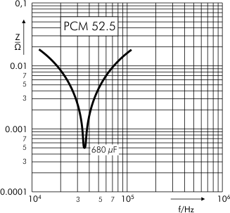
Varastossa
Tuote: 1140120
Tuotteita varastossa: 1 kpl